Cut Parameters
Fine tune each cut within a strategy using the following parameters. To edit cut parameters, select the ellipses in the edit column of the strategy dialogue.
Current Tool
Displays the currently selected tool. Select a new tool from the list to change the tool used.
Cut Type
Define how the cut will be generated relative to the geometry. There are 3 options, Rough, Clean, and Fine. The cut options are automatically determined by EnRoute based on the strategy type and cut order.
The first cut is always defined as a Rough cut and the second cut is automatically defined as a Clean cut. This setup allows the Rough cut to remove material around the part and the Clean cut to finish the final cutout.
A Fine cut can also be added which is intended to fit into corners and tight areas the Rough and Clean tool cannot reach.
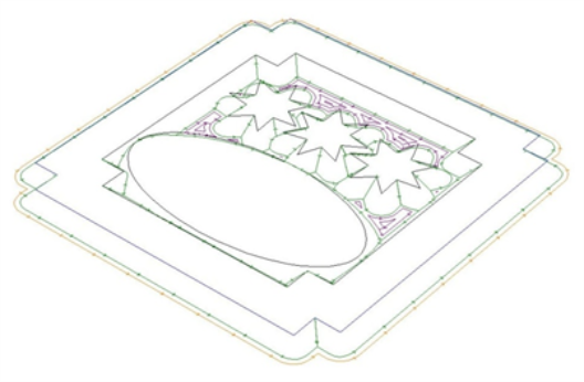
Below is an example of the same part with 3 different strategies. The first only uses a Rough cut. The second uses a Rough and Clean cut. The third part has a Rough, Clean, and Fine cut applied.
![]()
Depths
| Surface Depth | The distance from the top of the plate to the top of the design. Default is 0.0 |
| Final Depth | The depth of the cut measured from the surface depth. When surface depth is 0, Final Depth is the distance from the material surface. |
Passes
| Number | Number of passes that will be created. The minimum number of passes is automatically calculated by the Max Per Pass value and the Final Depth. Number cannot be set below the minimum value. |
| Max Per Pass | Maximum depth of each pass. The default is automatically calculated from tool dimensions, but can be decreased to control the depth per pass. |
| Actual Per Pass | Calculated from the Number of passes and the Final Cut Depth. If a Final Pass is used, the Final Pass Depth is removed from the Actual Per Pass value. |
| Final Pass | Define a final pass with a different depth than the other passes. Number of passes must be greater than 1. |
| Final Pass Depth | Depth of the Final Pass |
Width
| Width of Cut | Define an offset from the part surface a clean or rough cut will follow to leave material for a clean cut to remove on a second pass. A cut width of 0.0 will generate a Rough and Clean cut that trace the same surface of the part. A cut width greater than 0.0 will offset the Rough cut by the width, leaving additional material to be removed by the Clean cut. |
| Number of Steps | The number of passes required for a specified cut width. Automatically calculated based on the Max Step value and the Width of Cut. |
| Max Step | Maximum width of material that can be removed in one step. |
| Actual Step | Calculated based on the Number of Steps and Width of Cut parameters. |
| Shoulder | Create a step around the perimeter of the design. |
Feeds and Speeds
| Feed Rate | Speed the tool will move through the material when cutting |
| Final Pass Rate | If the Final Pass option is enabled, specify the speed for the final pass |
| Plunge Rate | Speed the tool will move down into the material |
| Dwell | A time delay that will cause the tool to pause between plunging into the material and feeding into the material |
| Spindle Speed | Speed of the spindle during cutting |
Direction
| Conventional | The tool will turn in the direction of travel. For a standard exterior cut along a contour, the tool will move in a counter clockwise direction. |
| Climb | The tool will turn against the direction of travel. For a standard exterior cut along a contour, the tool will move in a clockwise direction. |
Toolpath Entry and Exit Parameters
Define how the tool should move away from the finished edge when moving in and out of cut.
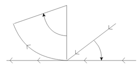
| Arc | Define an arc path for the tool to follow by specifying a Radius and Angle of the arc path to follow. The 3D Arc option can be enabled and a Lift defined to create a 3D entry/exit path. |
| Line | Define a straight line path for the tool to follow by specifying the Length and Angle away from the finished surface. The 3D Line option can be enabled and a Lift defined to create a 3D entry/exit path. |
| Combination | Create a combination arc and line entry/exit path by specifying Radius, Angle, and Length. The tool will follow a straight line to approach the finished surface and then arc into cut, or reverse for an exit path. |
3D Toolpaths
Create a 3D cut. A 3D toolpath must be created with a conic, tapered, or engraving tool. A 3D toolpath uses the beveled shape of the tool to create a beveled edge on the finished piece. The tool will also move into the corners as far as the tip dimension of the tool will allow.
EnRoute automatically monitors the type of cut and type of tool and will only allow 3D toolpaths to be enabled when appropriate.
The following image is an example of a piece cut with 3D toolpaths.